

Deutsche Version
|
Deutsche Version |
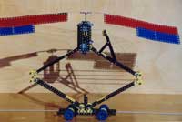
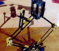
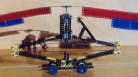
| This model of a 'slowmobile' was the winner of the second Prize in category 2 (a technical challenge) of the 'Competition Summer 2002', organized by the schraube-und-mutter.de website. The model needs 15 minutes for the distance of 1 metre (see rules)! Construktion: Ian de Lande Long, Seeheim System: Meccano |
||||
|
|
||||
| Ian de Lande Long about his model: |
|
|||
| Falling Metal - a Meccano Slowmobile Introduction This Meccano model (see pictures) which I call "Falling Metal" is designed for entry into the schraube-und-mutter.de 2002 Summer Competition (see rules). The model uses a falling weight (most of the model itself) to drive itself forward for slightly more than one metre. The rate of progress is limited by friction in the mechanism and by aero-braking. |
 |
|||
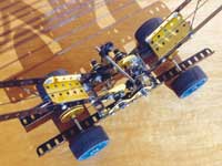
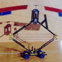
| The Model In order to have as much available energy as possible to overcome friction it is important that as much weight as possible is placed at the top of the model. The model consists of an open box supporting a vertical spool attached to approximately ten metres of cord. The box is massively built using four 5.5 inch girders joined by many short flat girders. The top and bottom of the box are formed by flanged plates offset a quarter of an inch from the raster of the rest of the box. |
 |
|||
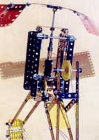
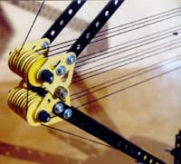
| Attached to the spool is a large fan and the whole is supported in the box by a thrust bearing. The thrust bearing - one of the most important features of the machine - consists of the end of one machine-ended rod rotating on the end of another machine-ended rod. The two rods are aligned within the bush of a bush wheel attached to the frame, the lower rod gripped by a grub screw in the bush. The point of contact of the two dome-ended rods is lubricated with light grease. This arrangement minimises friction (with the parts available to build the model) and permits the spool assembly to rotate very easily. |
 |
|||
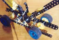
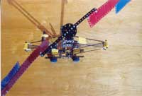
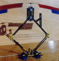
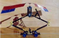
| The raster offset of the top and bottom of the box means that the centre of rotation of the fan is located on a vertical line through the centre of the model. The box is supported by a folding frame (pantograph). The lower arms of the frame are held at similar angles to the horizontal by gear wheels attached to the bottom of the arms. The box is held vertical by a similar arrangement of gears at the top of the upper arms. The lower arms of the frame are supported on a simple four-wheeled trolley with the lower arms (and therefore the rest of the upper structure) aligned fore and aft on the trolley. The trolley is designed to be as light as possible (using the parts which were available to build the model) and consists of four girders and four rod supports for the frame. Each rod support consists of two flat trunnions. |
 |
|||
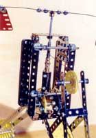
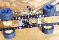
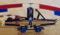
| As described so far, the box is free to move vertically but is constrained to remain over the centre of the trolley by the action of the pantograph (and its gears). In addition to the parts described above, the trolley uses two double-angled strips (padded with rubber grommets) to act as "end stops" for the box. A row of plastic pulleys is mounted on a horizontal axle attached to each arm close to where the upper and lower arms meet. The flat trunnions holding the axles are mounted so as to maintain the perforated strips (which form the main part of the arms) exactly above each other. As the box moves downwards, the pulleys at the front of the model move apart from the pulleys at the back. |
 |
|||
| The cord from the spool is passed over a feed pulley (see below) and wound horizontally to and fro across the pulleys attached to the arms. Four horizontals before the end of the cord, it is diverted (from its to-and-fro path) onto the drive mechanism for the trolley. For this diversion, the cord is passed over a pulley mounted in the centre of a frame-support rod and then over the drive pulley on the adjacent axle and then under the length of the trolley to the second drive pulley and from there back to the adjacent pulley on the (other) frame-support rod to complete the diversion. The cord is in contact with each drive pulley for a full half turn (ie for 180 degrees). After the diversion, the cord is passed as four horizontals over more of the pulleys attached to the arms, finally being secured to the frame at the end of the last horizontal. |
 |
|||
| In the "Competition Rig", not all the pulleys attached to the arms are used: the "motor" of the model contains 12 horizontals, eight before the drive pulleys and four after. Using rough measurements in inches (to match the Meccano half inch raster) it is possible to calculate the movement of the cord which drives the model. During the run of the model, the centres of the pulleys on the arms move from about 17.25 inches apart to 25.5 inches apart. So each horizontal takes up an extra 8.25 inches of cord during the run. Therefore four horizontals take up 33 inches of cord - which passes over the 1.5-inch drive pulleys attached to each main axle of the trolley. |
||||
| A 2-inch wheel is attached to one end of each main axle. The other end of each main axle carries a freely rotating 2-inch wheel. The ratio 2 to 1.5 means that the 33 inches of cord passing over the drive pulleys causes the model to move 44 inches (rather more than one metre) on its wheels. Unlike metal pulleys, the plastic drive pulleys (which are used to save weight at the bottom of the model), do not have a V-shaped profile so do not grip Meccano cord well - they allow it to slip. Therefore a small Meccano driving band, which has a square cross section, is stretched over each drive pulley (while taking care to ensure that there is no twist in the band). This gives two V-shaped profiles each with one rubber and one plastic face. The Meccano cord does not slip in one of these profiles. |
 |
|||
| Factors needing Optimisation During a run of the model, as the box falls each horizontal run of cord becomes longer and so draws cord from the spool. Drawing cord from the spool turns the fan. And the faster the fan turns the more energy must be dissipated to overcome air resistance. The aero-braking effect limits the rate of cord release and therefore the forward speed of the model. Reducing the diameter of the spool increases the number of turns per inch of cord which increases the number of turns affected by the aero-braking. So a small diameter spool is desired. Also, the arms of the frame need to be as long as possible (to increase the distance fallen by the box and) to give more potential energy for dissipation by aero-braking. At the beginning of the run, a one inch fall in the box draws about 1.25 inches of cord from the pulley into each horizontal. At the end of the run, a one inch fall draws about 0.125 inches of cord from the spool. So if the spool were merely a Meccano axle rod, at the start of the run the weight of the model would have less leverage on the fan than at the end of the run. For each inch of fall, the same amount of energy is available to overcome friction. So at the end of the run one might expect the model to travel faster than at the start of the run. Travelling fast is not good. |
 |
|||
| If we assume that friction is roughly constant or assume that it increases at low speeds, we expect that at the beginning of the run the effect of friction on limiting the speed of the model will be greater than at the end of the run. And this is confirmed by experiment. This means that at the end of the run, the aero-braking might be required to do more work than at the beginning. So at the end of the run we have energy being released faster than at the start of the run. Wasted energy at the end of the run is not good. We want the model to travel as slowly as possible at all times. And we want as much of the available energy as possible to be used to overcome the friction we have not been able to eliminate (by careful design, construction and lubrication). This is (at least partially) achieved by using a spool whose diameter varies along it length. At the bottom of the spool its diameter is that of a sleeve piece, above that its diameter is that of a coupling and finally its diameter is that of an axle. This changing diameter evens out the leverage (somewhat) over the run. |
||||
| The feed pulley (mentioned above) rotates freely on a axle held by some additional structure attached to one of the upper arms. The feed pulley acts as an intermediary between the spool and the first pulley attached to the end of the arm. During a run of the model the cord passes from the spool to the arm-end-pulley. However the important part of the feed pulley's operation occurs while the cord is being wound onto the spool: the position of the feed pulley (which varies as the frame unfolds) largely determines how the cord is laid onto the spool: it determines the diameter onto which the cord is wound. The exact position of the feed pulley relative to the spool is important - this is determined by the geometry of the structure which attaches the pulley to the arm. |
 |
|||
| So the spool shape combined with feed pulley position is another of the most important features of the machine. Ideally the spool would be conical (or better, follow a trigonometrical form related to the cosine of the angle of the frame arms as the cord is laid onto the spool). Using standard Meccano parts the best that can be achieved is a stepped spool. This means that at the beginning of the run one turn of the spool releases more cord into the horizontal than at the end of the run. |
||||
| Operation of the Model For the purposes of the competition, the model may be timed over a track (along a smooth, horizontal table or similar) which must be at least as long as the trolley plus one metre plus a bit extra. It is convenient to lay a tape measure along the track. In addition, clearance around the track is required for the rotation of the fan. The fan overhangs (fore and aft) both the trolley and pantograph. For the purposes of the competition, the movement of the front and back edge of the fan needs to be measured. However as the fan axis is constrained to remain over the centre of the trolley, the front edge of the trolley forms a more convenient reference point. |
 |
|||
| The model is operated by placing the front edge of the trolley a few centimetres after the "finish line" and winding the fan backwards (clockwise when seen from above). This causes the cord to be wound onto the spool. The movement of the cord over the drive pulleys causes the model to move backwards. It also causes the folding frame to raise the box supporting the fan. The winding process must be continued until the front of the trolley reaches the "start line" (one metre from the "finish line") and the fan is aligned longitudinally with the track. At this point it may be necessary to re-align the trolley with the track so that it will run accurately along the track. The model is started by releasing hold of the fan. About a quarter of an hour later, the front of the model will cross the "finish line". |
 |
|||
| Further Developments The reason that friction is mentioned here so often is that its irregular and unpredictable nature dominates the performance (the slowness) of the model. As the model is developed and some friction overcome, there is immediately a temptation to add another horizontal to the "motor". This increases the need for cord to be drawn from the spool and slows the model. This is good. But it also increases friction again. This is bad. And it may be very bad - the model stalls before completing the one metre course. Stalling is most likely at the point in a run where the leverage on the spindle suddenly decreases. This occurs as the cord unwinds past a step in the spool. It is also likely when a knot in the cord has to pass over a pulley. (The maximum length of continuous Meccano cord available to build the model was 14 foot 9 inches. So there are several knots in the competition model.) |
 |
|||
| The model structure is on the limit of what can be done in two kilograms of Meccano. Any extra weight which can be saved from the bottom of the model is moved to the top of the model (as 5.5 inch perforated strips attached as ballast to the box). This means everything is too lightly built and even the comparatively small tension in the horizontal of cord tends to warp the model out of true (thereby increasing friction). Starting with the first horizontal after the spool, the tension in the cord increases with each pulley (friction at the pulley bearing has to be overcome): each horizontal is at a slightly different tension from all the others. These differences in tension make it very difficult to rig the pulleys so that the forces are evenly distributed on the frame. Development of the model continues. I am looking at using more pulleys to get more horizontals and am experimenting with different orders for the rigging (to try to distribute the tension in the horizontal to avoid warping the frame). The more cord in the model, the longer it takes to unwind and so drive the model over one metre. But the more pulleys there are the more friction. But that's engineering. |
 |
|||
| Conclusion Hurrah! We built this model with Meccano. Look at it - it works! The original idea of a slowmobile was brilliant and taking part in the competition has given me much pleasure. Meccano boys have more fun than other boys! I would like to thank all those who have encouraged me to take up this hobby again (MAdeLL, AMJH, NAK, TCPB). And I heartily thank the people at schraube-und-mutter.de. Ian de Lande Long |
 |
|||
| Imprint | ||||
| Dieter Müller | ||||
| Last update: 2002-10-06 | ||||
| Namen und Warenzeichen können geschützt sein. | ||||